
#Force diagrams free
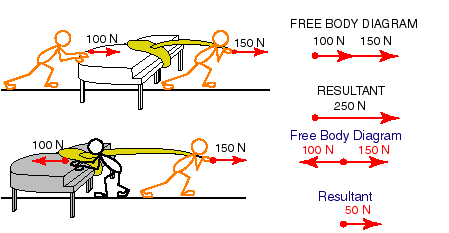
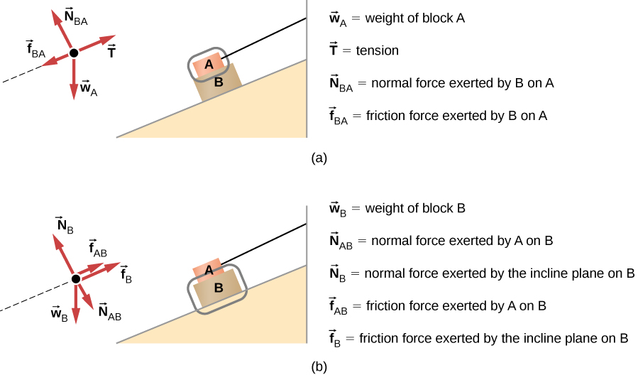
A free body diagram for each mass is shown in Figure 2.įigure 2: Left: mass hanger m 2 Right: block m 1 The mass can usually be simplified to a dot representing the object’s center of mass, and the forces are then vectors extending out from the dot in the direction they are applied. See Figure 1 for a diagram of the demo set up.įree body diagrams show all of the forces acting on each individual mass in a system. In this demonstration, a wood block is pulled up an inclined plane by masses hanging from a pulley attached to the ramp. The forces can then be analyzed easily using Newton’s second law of motion. The calculations illustrated in this section can actually be performed to define the service factor necessary to prevent gear mesh failures resulting from axial-thrust transmission.Free body diagrams are a great way to simplify a complicated situation involving many different types and directions of forces. Replacement gear elements can be purchased with a larger service factor than listed in AGMA 421.06.

This requires that the initial system axial alignment take into account the thermal expansion of both coupled shafts. However, the purchaser should recognize that high axial movement cannot be accommodated by diaphragm couplings. Diaphragm couplings accommodate misalignment while transmitting power by material flexure. The coupling can be replaced with an axially soft diaphragm coupling which transmits little or no axial thrust. Replace couplings with large tooth pitch diameter gear couplings. Using adequate safeguards, such as temperature thermocouples embedded in the thrust-bearing material and connected to a shutdown system, potential failures thus confined to the thrust-bearing replacements are certainly less costly and less time consuming than gear-tooth failures.

This, in effect, makes the thrust bearing the weak link, or sacrificial component.
#Force diagrams crack
The depth of the beam is h, the inclination θ of the diagonal crack is defined by the distance x and the effective tensile strength of the concrete is f tef. The resultant applied load (W dat) cr acts at a distance e from the focal point. Furthermore, (W dat) cr is the resultant of the applied loads acting on the free body of length L 0 when (V dat) cr is acting and, hence, it is also proportional to (V dat) cr such that (W dat) cr = K w(V dat) cr. Therefore, (M dat) cr is a function of (V dat) cr, that is (M dat) cr = K M(V dat) cr. Hence (M dat) cr is the moment at the datum point when (V dat) cr is acting.

The shear load at the datum point to cause cracking (V dat) cr is our reference stress resultant. The axial force in the longitudinal reinforcement is ignored as prior to cracking the stresses in the reinforcing bars are negligible. The beam is assumed to be prestressed with the prestressing tendon at a vertical distance d ps from the focal point and a prestressing force of F ps. It is necessary to determine the shear load at the datum point (V dat) cr, that will cause the diagonal crack at an angle θ to form, that is the vertical shear to cause cracking. Adapted from Winter, 1990, Table 3.1, pp.


 0 kommentar(er)
